

Different Types Of Dimensioning In Engineering Drawing
Types of Dimensions in an Engineering Drawing
![]()
In this article, we will take a look at all the different types of dimensions available inside a draftsman's toolbox.
Linear Dimension
The simplest dimension represented in a drawing is the length of a feature. It just says the linear distance between two features in a component.

Here, 70 is the distance between the two extreme sides of the above object. It is represented with an arrow.
Chain Dimension
You would have noticed there are two holes in the rectangular bar shown above. Hence, we also need to position the holes inside the rectangular bar with proper dimensions.
That's when we need to resort to the chain dimensions.
There are two types of Chain Dimensions.
Type 1:
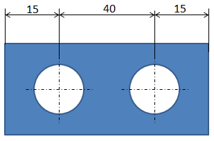
Just place the dimension as a series starting from one extreme end and moving on till the other end.
Type 2:
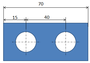
This is the correct method to fix the chain dimension.
Here, you fix the overall dimension first, i.e., the longest dimension from one extreme end to the other extreme end. Then, you proceed with the smaller dimensions.
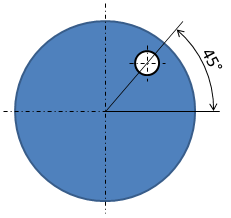
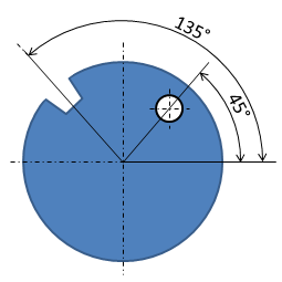
Angular Dimension
This is how you define the angle. Unlike the linear dimension, here the arrow is curved which is understandable.
Also, the chain of angular dimensions will look like below.
Not to Scale Dimension
When a component is very large in size, you can reduce the scale of the feature in the drawing. Such as 5:1, 10:1, 20:1, and so on.
But what if you want to represent a 100 meters long wire in a drawing?
If you are trying to reduce the scale so as to represent the entire wire length inside the drawing, then the diameter of the wire which is 5–10mm will be hardly visible in the drawing.
Right? That's why we represent this way.
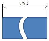
Also, for the wire, the cross-section remains the same throughout its length. Hence, there is no need to represent the entire length of the component either.
That's why we just show the ends of the component and represent the dimension with an underline, which means "Dimension not to scale".
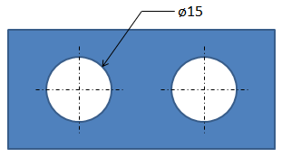
Diametral Dimensions
The hole diameter is different from the normal dimension.
A hole just looks like a rectangle in the side view. Hence, we need to imply to the reader that it is indeed the diameter of the hole.
That's why we use the diameter symbol "ø" in front of the dimension.
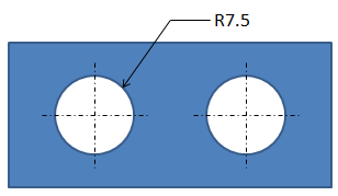
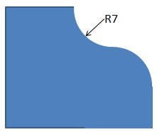
Radial Dimensions
Similar to diametral dimensions, for radial dimensions, we use "R" in front of the dimension to represent the radial dimensions.
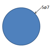
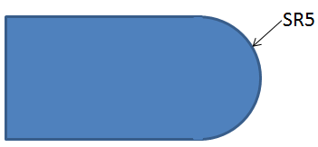
Spherical Dimensions
A Circle on a drawing can be perceived as a sphere, or as a cylindrical hole.
A Sphere is circular in 3-dimensional space, whereas a hole is circular only in a 2-dimensional space. Hence, it is necessary to differentiate between a circular radius(R) from a spherical radius(SR) in a 2D drawing.

We use "S" as a prefix. For a spherical radius, it is "SR" and for spherical diameter, it is "Sø".
So that is all about the different types of dimensions that are used in any drawing.
Dimensions alone are not enough to represent a component completely. To specify the position and orientation, we need to resort to GD&T.
Lets discuss that in the next post.
Different Types Of Dimensioning In Engineering Drawing
Source: https://medium.com/tolerance-analysis/types-of-dimensions-in-an-engineering-drawing-eafff6355a55
Posted by: gallawaynoter1965.blogspot.com
0 Response to "Different Types Of Dimensioning In Engineering Drawing"
Post a Comment